Solving Difficult Molding Problems for High-Precision Solenoid Valve with Moldex3D
Edited by James Zhou, Engineer at Technical Support Team, Moldex3D Eagle Industry Taiwan Co., Ltd. (EKK) that cooperated with Japan’s イーグル Industry Co., Ltd. was built in 1979. EKK company is an integrated component manufacturer, providing high-quality products, solutions, and comprehensive services in the Asia-Pacific region. Its major products can prevent fluids such as liquid gas from leaking during rotating operation in different machineries, such as automobiles, locomotives, houses, ships, etc. (Source) The product in this case is a solenoid valve used in automatic flushing urinals. The product material is crystalline plastic, POM, shown in Fig. 1. The product has thickness restrictions and high dimension accuracy requirements. Therefore, the designer used Moldex3D to determine the optimal gate locations and optimize the process conditions. The main objectives were to achieve: (1) high precision for the specific lip surfaces, (2) no surface defects, and (3) less internal void caused by uneven product thickness, as shown in Fig. 2. Used Moldex3D to improve the defects of the product by determining the optimal gate locations, and optimizing process conditions The main purpose of this study is to solve three molding challenges of the urinal solenoid valve, including dimensional requirements for lip surfaces, to eliminate surface defects, and to decrease voids. Fig. 3 shows the lip surfaces of the original product. Poor roundness caused by uneven gloss may cause air leakage and abnormal sounds during operation. Therefore, the EKK team used Moldex3D to redesign the gate locations. As shown in the newly designed product, the number of air traps was significantly reduced after the gate design optimization. More importantly, the lip surface pressure was more uniform, and the surface roundness also met the requirement of R0.02 ~ R0.05 mm, as shown in Fig. 4. Secondly, it was necessary to eliminate the appearance defects. In the original process conditions, the flow rate setting of the first stage was too high. Thus, high shear heating and jetting phenomena occurred when the melt passed through the gates with smaller cross-sections. Therefore, the team reduced the flow rate at the gate from 40cm3/sec to 15cm3/sec, and then the jetting defect had significantly improved (Fig. 5). However, the reduced flow rate was too slow and may cause the melt temperature to decrease, so melt front hesitation would occur. After the flow rate increased, the material temperature was then raised by 7°C. Fig. 6(c) shows the product surface is smoother and with less hesitation flow mark. The uneven initial shear stress caused unsmooth or uneven gloss product surface. The best improvement method was to completely release pressure of the cavity before melt solidation. Thus, the EKK team added one more stage after the third packing pressure stage to slowly release pressure and avoid the internal shear stress. The stress marks were successfully solved after the process optimization, as shown in Fig. 7. The initial void issue caused by the thick part and serious shrinkage may also affect the product rotation balance and part strength. Fig. 8 shows the cross section of voids through X-ray, and those void positions are consistent with the simulation result of volume shrinkage higher than 9%. Therefore, to attain a high strength product, the part volume shrinkage should be ensured to less than 9% during the optimization process. As for the effective packing time, the part gate freezes at 14 seconds. Fig. 9 (left) shows the melting material distribution. In the original process, the packing pressure was set 20 seconds, it meant the cavity pressure could not be released after 14 seconds. Thus, it was not feasible to set an additional buffer section at the last stage of the packing pressure parameter to release the pressure. Thus, the packing pressure was then set for 11 seconds, at which there were a few molten states at the gate area. So that the product would have continuous pressure compensation, stress was released and shrinkage was reduced effectively. Finally, after the molding process optimizations, the volume shrinkage was successfully improved, and the voids was decreased. The void simulation showed a similar result with the actual X-ray photo (Fig. 10). The EKK team used Moldex3D to preview the problems that may occur in the product. Through the simulation results of plastic flow front patterns, they were able to determine the optimal gate locations to avoid melt jetting. By modifying the process conditions of packing pressure and number of stages, they improved the lip surface roughness and solved flow/stress mark issues. They also successfully reduced the voids and improved product strength by adjusting the packing time.  zhuzhou haokun hard materials CO.,LTD , https://www.hkmetalpowder.com
Executive Summary
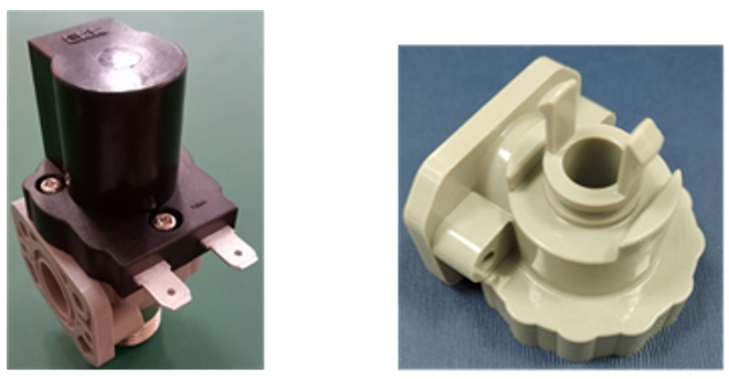
Fig. 1 HCG urinal solenoid valve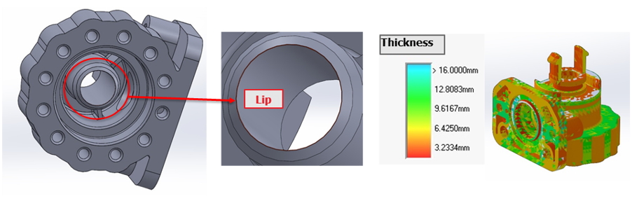
Fig. 2 Lip surface and thickness range of the product
Challenges
Solutions
Benefits
Case Study
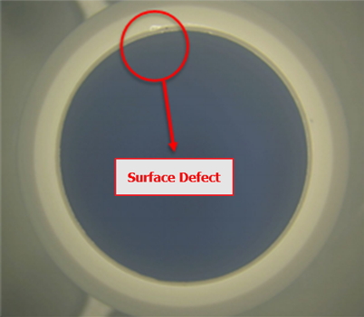
Fig. 3 Lip defects of the original product
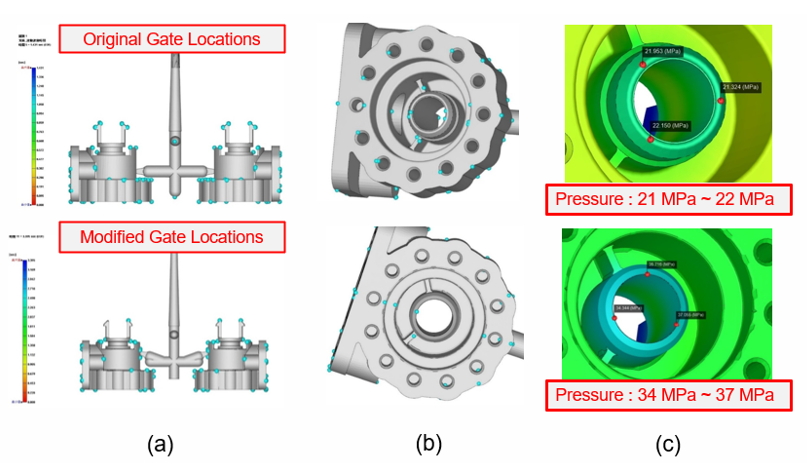
Fig. 4 Analysis results of gate location design changes: (a) gate locations, (b) air traps displacement, and (c) pressure results of the filling stage.
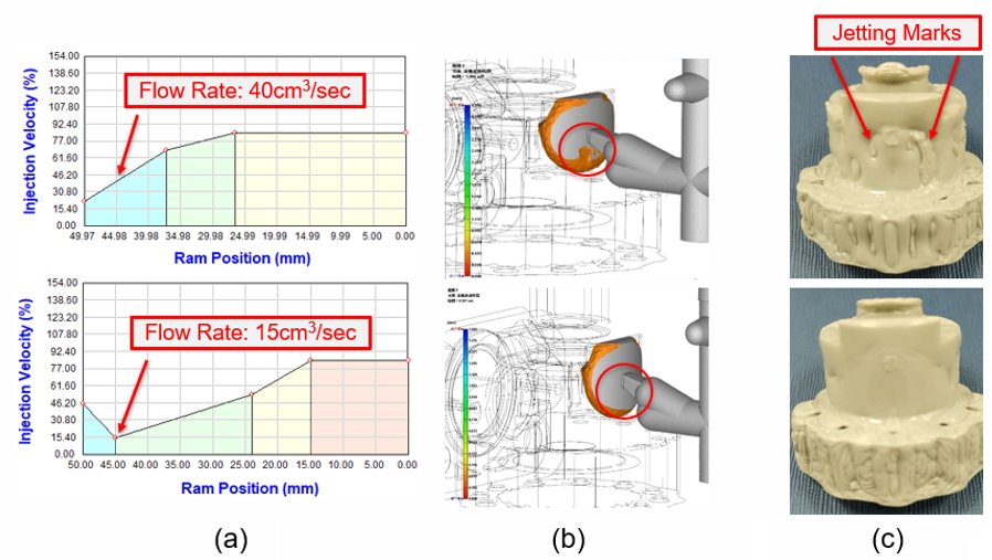
Fig. 5 Comparing the jetting issue of the product: (a) the flow rate changed to be low when the melt passed into the gate, (b) the flow front time was improved, and (c) the actual product had less jetting marks.
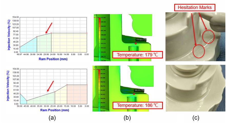
Fig. 6 Comparing the hesitation flow marks of the product: (a) the flow rate of the melt passing into the mold cavity was increased, (b) the melt working temperature raised by 7°C, and (c) the actual product had less hesitation.
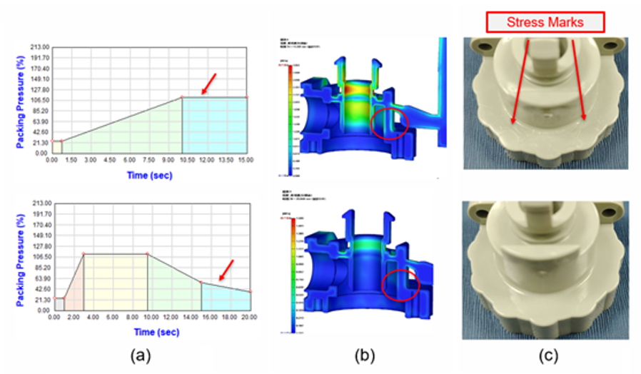
Fig. 7 Comparing the stress mark issue of the product, (a) the new process conditions with pressure releasing at the final stage, (b) the pressure setting revised part with less shear stress, and (c) the new actual product is with perfect and smooth appearance.
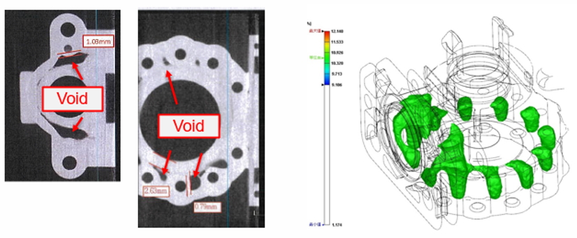
Fig. 8 The X-ray scanned void result of the original product (left) and the simulation result of volumetric shrinkage higher than 9% (right)
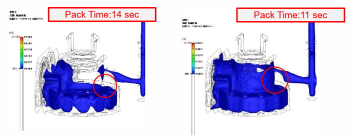
Fig. 9 The results of the melting area at the end of the packing time: 14 seconds and 11 seconds, without releasing packing stages settings
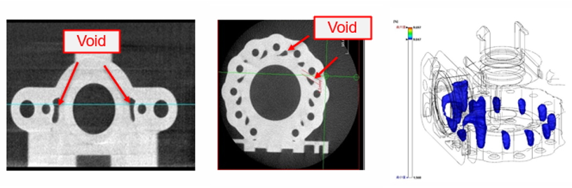
Fig.10 The X-ray scanned void results of the optimized products (left) and less volumetric shrinkage shown in simulation (right).
Results